

Turbine Types
As previously discussed, two broad turbine types exist – impulse and reaction. The following section addresses the style of turbine that can be installed at small hydropower sites in Wyoming.
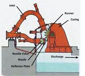
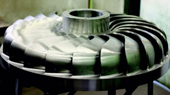
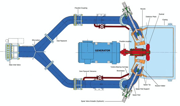
i) Pelton Turbine
Pelton turbines, as shown in Figure 34 and Figure 35, are impulse turbines where one or more jets focus the water flow controlled by needle valves into buckets attached peripherally on the turbine runner. Pelton turbines are best suited in high head applications. Since the head is typically high, the flow rate tends to be low and can be as little as 0.2 cfs. The turbine requires the flow through the inlet to be highly pressurized; as a result the penstock design is crucial and should be designed to handle the high pressures. In case of an emergency stop of the turbine, the jet may be diverted by a deflector so that it does not impinge on the buckets and the runner cannot reach runaway speed. In this way the needle valve can be closed very slowly, so that overpressure surge in the pipeline is kept to an acceptable level. A Pelton turbine can have multiple jets, up to six, that can maintain high efficiencies and greater power production under variable flows. The jets and buckets are designed to create minimal loss and to keep exit velocities to a minimum; this leads to a potential efficiency of 90 percent, even in small hydro applications. Multi-jet turbines can operate very efficiently at flows as low as 10 percent of the design flow as shown in Figure 33. Since Pelton turbines discharge to atmosphere they are not well suited if downstream pipeline pressures are required, such as a municipal system installation.
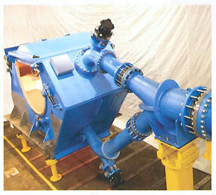
Source: Gilkes Hydropower Systems
Source: “Guide on How to Develop a Small Hydropower Plant” European Small Hydropower Association 2004
ii) Turgo Turbine
The Turgo turbine, as shown in Figure 36 and Figure 37, is an impulse turbine developed from the Pelton turbine and utilizes much of the same technology. Turgo turbines are typically utilized for lower heads and higher flows than Pelton turbines. The efficiency of a Turgo is lower than the Pelton, but retains the ability to support a broad flow range. The main physical differences between the two relate to the flow path of water through the turbines and the cup shape on the runners.
Source: Gilkes Hydropower Systems
Source: Gilkes Hydropower Systems
iii) Cross Flow Turbine
The cross Flow turbine, as shown in Figure 38 and Figure 39, is an impulse turbine named for the way the water flows across the runner. Most cross flows have two or more inlet guide vanes and can maintain a high efficiency over a wide range of flow rates. By altering the operation of the inlet guide vanes to better suit flow conditions, flow can be directed at just a portion of the runner during low inflow, or the entire runner when higher flows dictate. As evident from the efficiency curve, the Cross Flow is able to maintain a consistent efficiency. Cross flow turbines can operate under a wide range of head, spanning from approximately 6 feet to 650 feet, although it becomes less effective for heads greater than 130 feet. The major advantage of a cross flow turbine is it can operate efficiently over a wide range of flows, as little as 1.5 cfs, up to 175 cfs, making it well-suited for seasonal flows. The self-cleaning design and standardized componentry lends to very little maintenance and prolonged life. Typical power outputs range from 5 kW to 100 kW, though they can actually be up to 3 MW on the very largest systems; however, there are generally better turbine choices for these higher power outputs.
Source: Renewables First www.renewablesfirst.co.uk
Source: Renewables First www.renewablesfirst.co.uk
iv) Francis Turbine
The Francis turbine, as shown in Figure 40 and Figure 41, is a reaction turbine and the traditional turbine for standard, medium head. It has a reliable, simple construction with adjustable guide vanes and fixed runner blades. The efficiency curve shows the Francis turbine has a higher peak efficiency than other turbines but has a narrow operating range. The inlet water flow is always radial, and the outlet is axial through a draft tube. The water enters the turbine by the spiral scroll case and flows through adjustable guide vanes or wicket gates, whose function is to control the water flow into the runner and adapt the inlet angle of the flow to the runner blades angle. Guide vanes can be used to shut off the flow to the turbine in emergency situations. A butterfly valve on the turbine inlet is also an emergency means to shut off the flow to the turbine. The runner blades on a Francis turbine are designed to throttle the flow during a run-away event; however, the sudden reduction of flow and thus velocity will create a transient surge and cause water hammer in the pipeline. The amount of increased pressure would depend on the change in the water velocity, and an extensive transient surge analysis is required to determine the pressure increase and design of surge protection tanks or other design measures. The Francis turbine can typically operate in run-away mode for a limited amount of time. This allows for the slow closure of the wicket gates or turbine inlet valve and turbine shut down. The Francis turbine can be used in-line with an existing pipeline and has the ability to maintain downstream pressure requirements. This application is useful in municipal installations where pipeline distribution pressures are required.
Source: Gilkes Hydropower Systems
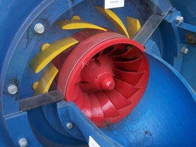
Photo courtesy of Stahlkocher at de.wikipedia
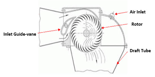
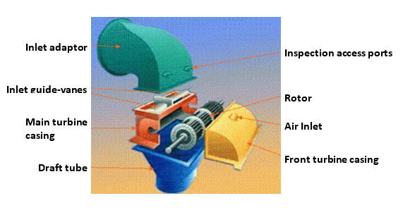
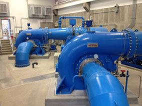
v) Kaplan Turbine
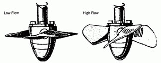
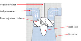
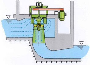
The Kaplan turbine, as shown in the figures below, is a reaction turbine that is highly adjustable in both the pitch and the runner blades as well as the inlet guide vanes. This adjustability increases efficiency and allows for a larger flow operating range. Figure 42 shows the varied positions of the runner blades to accommodate changing flows. A Kaplan is ideal for low head sites with net head ranging from 10 feet to 65 feet. Since Kaplan turbines can operate under low heads, optimally the turbine will have large flows through the turbine. The peak discharge for which the Kaplan operates ranges from approximately 100 cfs to 1,050 cfs.
Source: Renewables First www.renewablesfirst.co.uk
Source: Renewables First www.renewablesfirst.co.uk
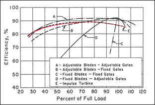
The turbine works by utilizing flow through the inlet guide vanes that acts upon the propeller-like blades to create shaft power. While the Kaplan is relatively expensive compared to other turbine types, its adjustability and higher efficiency adds to its appeal. Different versions of the Kaplan are available for varying conditions, which can reduce the price of the turbine. Kaplan turbines that have both adjustable inlet guide-vanes and adjustable rotor blades are known as being “double regulated” or full-Kaplan turbines. The variant of Kaplan turbines that only have adjustable inlet guide-vanes or adjustable rotor blades are known as semi-Kaplans. Although the performance of semi-Kaplans is compromised when operating across a wide flow range, for applications where the flow does not vary greatly, they can be a more cost-effective choice. Figure 45 shows how the efficiency varies across the operating flow range for a full-Kaplan (curve A), a semi-Kaplan with adjustable blades (curve B) and a semi-Kaplan with adjustable inlet guide-vanes (curve D). It also shows the efficiency curve for a propeller turbine, a Kaplan with both fixed blades and fixed inlet guide-vanes (curve C), and an impulse turbine, such as a Pelton (curve E).
Source: Hydropower Engineering Handbook Arndt and Gulliver 1991
Source: Renewables First www.renewablesfirst.co.uk
vi) Pump-as-Turbine
The pump-as-turbines, as shown in Figure 46, are reaction turbines that utilize a standard centrifugal pump running in reverse. Instead of using an electric motor to drive the pump, a pump-as-turbine operates by moving the flow through them in reverse, which causes the motor to become a generator. In most cases, it is more reasonable to have a direct drive, in which the pump shaft is connected directly to the generator, rather than fitting the system with a belt drive. Pump-as-turbines are generally fixed flow, and multiple turbines can be installed to account for varying flows. Pump vendors (e.g. Cornell Pump) have tested a range of pumps running as turbines and can provide a standardized product often less expensive than a custom Francis or Pelton turbine. Several different sizes and configurations are available and can operate under a large range of head and flow. Since pump-as-turbines are fixed flow, they operate in “on/off.” When the flows exceed the design flow of the turbine they are switched on, and any flows greater than the design flow of the turbine would be bypassed. When the flow rate is less than the design flow of the turbine, the unit is switched off, and power is not generated. Pump-as-turbines are not well-suited for variable flow conditions. If flow rates are variable, the pump-as-turbines could start up and shut down multiple times causing stress on the turbine, generator, and piping, which could reduce the overall life of the equipment. Since pump-as-turbines are reaction turbines, surge pressures in the pipeline must be considered when the turbines shut down. Pump-as-turbines are well-suited for agricultural installations at the base of a center pivot where flow rate is consistent.
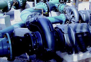
Source: Cornell Pump Company
Generator
The generator converts the rotational power from the turbine shaft into electrical power. Efficiency is important at this stage as well, but most modern well-built generators deliver high efficiencies. There can be big differences in the type of power generated, however. Direct current (DC) generators can be used with very small systems but typically are augmented with batteries and inverters for converting the power into the alternating current (AC) power required by most appliances. AC generators are normally used in all but the smallest systems. Common household units generate 120 VAC (volts AC) and 240 VAC, which can be used directly for appliances, heaters, lights, etc. AC voltage is easily changed using transformers, which makes it relatively simple to drive other types of devices or transmit over long distances. Depending on power requirements, either single-phase or three-phase AC generators are chosen in a variety of voltages. Larger generators are typically three-phase and 480 volts. There are two main types of generators: induction and synchronous. Induction generators rely on the electric grid to control the speed and frequency; synchronous generators monitor grid frequency and voltage and automatically adjust generation to match. If the electric grid goes down, induction generators have to be shut-down to prevent “freewheel” and will not operate; synchronous generators can be designed to continue to operate if the grid goes down. Induction generators are more common in micro-hydro applications and are generally less expensive than synchronous generators. Synchronous generators are necessary in larger hydropower installations and off-grid applications.
Controls
Turbine and generator controls are typically supplied with the water-to-water package, but there are different types of controls that can be used for different applications.
i) Grid Interconnection Controls
Grid interconnection controls, including switchgear, synchronize frequency and voltage to enable coupling with the grid. It will also safeguard both equipment and the grid in case of failure. The system will monitor the grid frequency and voltage to automatically adjust generation to match. This is a fundamental interconnection requirement for all utilities. Additional capabilities may be included in customized controls including water level monitoring and operation of flow control valves. Switchgear and transformers are used to step-up the generated voltage to line voltage for distribution to the grid.
ii) Emergency Shutdown System
The ability of the system to disconnect automatically is also a fundamental interconnection requirement. If the grid goes down, the generator must disconnect from the grid within two seconds to prevent additional power from feeding back into the grid for the safety of line workers and general public. The controls will detect the loss of power and automatically disconnect the generator. Once the generator is no longer experiencing a load, it will tend to increase speed if the turbine is still passing water and turning the generator. If the turbine is allowed to spin at runaway speed, there is potential it will spin too fast and water will not be able to pass through the turbine. The sudden reduction of velocity in the pipeline can cause a catastrophic pressure surge and can also damage the generator if allowed to spin freely. The emergency shutdown system will protect the system from overspeed. There are several safeguards that can be included in the system depending upon turbine type. As described above, different types of turbines are better suited to remove water from entering the turbine and spinning the runner. Impulse turbines use deflectors to simply deflect the water from the runner in case of emergency shutdown. The control valves can then be closed slowly to minimize pressure surges in the pipeline. Reaction turbines need to shut down slowly and water flow stopped through the penstock or directed away from the penstock. This can be controlled by automatic valves that close at a controlled rate to prevent an excessive pressure surge. Surge tanks are often commonly installed with reaction turbine systems.
iii) Off Grid Applications
As discussed previously, the majority of small hydro applications are interconnected with the grid and use the grid to control and regulate the frequency and voltage of the generator. Without the grid to regulate the generator, a much more site-specific assessment is needed to determine equipment needs to ensure safe, effective operation. Generally, a governor or load management system is needed (also called balance-of-system). A load management system can distribute generation to loads according to preset priorities and includes one load to shed excess generation. The system is used to condition the electricity, safely transmit the electricity to the load that will use it, and store or shed the electricity. Loads to shed excess generation can include battery charging or heat sinks such as water or ground heaters. A governor is necessary to balance varying loads and generation that do not have the benefit of the grid. Depending on the needs of the system, load management systems can account for half of total system costs.
System Costs
Generalizing the cost for turbines is difficult, as they often are designed specifically to accommodate individual site conditions. This is particularly true for units above 100 kW. Significant cost savings can be achieved if the hydroelectric system is installed at a site with existing civil infrastructure, such as a pipeline or other conveyance method and diversion structure. The appendix contains a list of turbine manufacturers, and when contacted directly with detailed site conditions (head and flow) of the proposed hydro site, an appropriate quote can be obtained.
The Electric Power Research Institute (EPRI) published a report, Quantifying the Value of Hydropower in the Electric Grid Plant Cost Elements in 2011.[i] This report includes cost estimate formulas for reconnisence level hydropower development projects and is useful to estimate development costs of a hydropower facility. These cost formulas are generalized and adequate for reconisence level studies; however, more detailed cost estimates should be used when designing and analyzing project feasibility. Table 2 lists the cost elements typically associated with the development of small hydropower installations.xv
According to the EPRI, the supply costs for the turbine, generator (lesss than 100 kW), and controls package can range from $1,000 to $2,000 per kW depending on unit type and operation, and installation costs can range approximately 50 percent of the equipment costs. As a rule of thumb, the civil works costs are less than or equal to the equipment costs (turbine, generator, and controls), and the total capital costs can range from $2,000 to $8,000 per kW of installed capacity, depending on the system’s capacity and location.xv
Table 2: Probable Cost Elements for Small Hydropower Facilities
| Project Site: TBD | |
| Typical Equipment Alternative: TBD | |
| Typical Installed Capacity: TBD kW | |
| Preparation of Final E/M Design | $ |
| Permitting/Mitigation | $ |
| FERC Small Conduit License Exemption | $ |
| FERC Qualifying Facility Self Certification | $ |
| Interconnection Application | $ |
| FERC Small Conduit License Exemption | $ |
| Other Permits and Miscellaneous Fees | $ |
| Legal Fees | $ |
| Acquisition of Access and Rights of Way | $ |
| Cost of Project Components | |
| Power Transmission | |
| Interconnection Costs | $ |
| Service Transformer | $ |
| Secondary Service, Disconnect and Metering | $ |
| Hydropower Plant | |
| Turbine Generator & Controls Supply | $ See Comment 1 |
| T/G Installation and Other E/M Modifications | $ See Comment 2 |
| SCADA Input | $ See Comment 3 |
| Structural and Site Work Allocation | $ See Comment 4 |
| Mobilization and Demobilization | $ |
| Temporary Facilities and Equipment Rental | $ |
| Miscellaneous | $ |
| Subtotal Project Components | $ |
| Field & Technical Support @ 10% of Above Subtotal | $ |
| Profit, Insurance, Bonds, etc. @ 15% of Above Subtotal | $ |
| Subtotal | $ |
| Contingency @ 20% of Above Subtotal | |
| Total Construction Costs | $ |
| Total Project Costs ($) | $ |
| $ See Comment 5 | |
| Comment 1: The supply costs for the turbine, generator, and controls package can range from $1,000/kW to $2,000/kW depending on the unit type, operating head/flow range, and required protections. Turbines are assumed to be Cornell type, in-line horizontal direct drive configuration. Generators are assumed to be induction type. | |
| Comment 2: Equipment installation can range approximately 50% (+/-) of the equipment supply costs. | |
| Comment 3: SCADA input can range approximately $10,000 to $15,000. | |
| Comment 4: As a rule of thumb, the civil works costs should be less than or equal to the equipment costs. | |
| Comment 5: The total project costs can range approximately $2,000/kW to $8,000/kW depending on specific site characteristics and impacts to existing infrastructure. | |
[i] Quantifying the Value of Hydropower in the Electric Grid: Plant Cost Elements. EPRI, Palo Alto, CA: 2011