

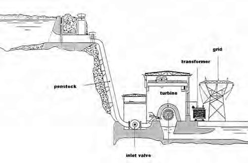
Hydropower facilities consist of electromechanical equipment that converts the potential energy of the water into electricity. Typical electromechanical equipment includes inlet gate or valve, penstock, powerhouse, turbine, drive system, generator, governors and control system, switch gear, protection system, and power and current transformers. Many small hydropower systems, particularly micro hydropower, are sold as “water-to-wire” packages. For water-to-wire packages, the manufacturer/supplier will supply all of the equipment – turbine, generator, controls and low voltage switchgear – as a package according to the specifications and interconnection requirements. The civil infrastructure such as intake, penstock, and powerhouse are not included in the water-to-wire package.
Intake Structures
The intake is typically the highest point of the hydro system, where water is diverted from the waterway into the pipeline that feeds the turbine. In many cases, a small dam is used to divert the water. The dam, in most large hydro projects, also creates the head necessary to drive the turbine. A water diversion system serves two primary purposes. The first is to provide a deep enough pool of water to create a smooth, air-free inlet to the pipeline. Air reduces power and can cause damage to the turbine. The second is to remove dirt and debris. Screens or trashracks can help stop larger debris such as leaves and limbs, while a settling zone will allow dirt and sediment to settle to the bottom before entering the pipeline. This helps reduce abrasive wear on the turbine.
Penstock
The pipeline, typically called the penstock, is responsible for conveying water to the turbine and serving as the enclosure that creates pressure with increasing vertical drop. In effect, the penstock focusses all the water power at the bottom of the pipe where the turbine is typically located. Pipeline diameter, length, and routing all affect efficiency, and there are guidelines for matching the size of the pipeline to the design flow of the turbine.viii As described in the previous section, a small diameter pipeline can considerably reduce the available power output, even though it can carry all available water.
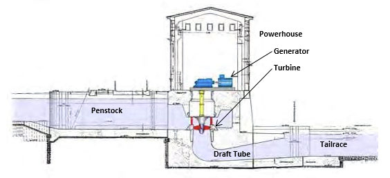
Powerhouse
The powerhouse is simply a building that houses the turbine, generator, and controls. The size and configuration of the powerhouse is dictated by the equipment configuration and landscape of the site. For example, a micro-hydropower system may not need any type of enclosure. Generally, the larger the system, the more civil infrastructure is required. The necessary equipment needs to be configured in an efficient manner with adequate clearance for installation and maintenance. Turbine manufacturers can give recommendations about powerhouse size requirements clearances and offsets between equipment.
Since hydro turbine and generator equipment has substantial weight, properly designing the powerhouse foundation and structure to handle the loads to which it will be subjected must be considered. Thrust blocks to support the penstock and turbine assembly should be designed to handle the loads and vibrations caused by the turbine. The turbine’s discharge channel (tailrace) is commonly integrated into the foundation and requires placement consideration when designing the powerhouse foundation. Access to the equipment must also be considered when designing the powerhouse. A permanent crane may be necessary to lift and place the equipment within the powerhouse, Figure 28 and 29 show examples of a powerhouse for a reaction turbine and impulse turbine, respectively.
Source: “Guide on How to Develop a Small Hydropower Plant” European Small Hydropower Association 2004
Source: “Guide on How to Develop a Small Hydropower Plant” European Small Hydropower Association 2004
Reaction turbines discharge water through a tailrace incorporated directly into the powerhouse foundation; whereas, an impulse turbine powerhouse discharges the tailwater directly into an open air excavation rather than a tailrace.
Turbine Selection
The type and size of hydropower turbine can be selected, once the available head and flow conditions are determined. This guide describes the most common turbines used in small hydropower applications and provides a general understanding of how the turbines operate. There may be applications where multiple turbine types will work with the given site conditions, and a turbine manufacturer or supplier (listed in the Appendix) can help in selecting an appropriate turbine.
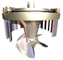
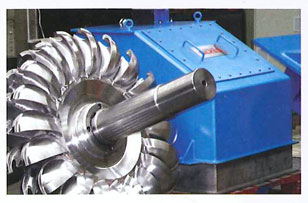
Hydro turbines are categorized into two groups: impulse turbines and reaction turbines, whose difference relates to the way energy is produced from the inflow. In a reaction turbine, the water pressure can apply a force on the face of the turbine runner blades, which decreases as it proceeds through the turbine. The turbine runner blades are fully immersed in water flow and must be encased in a pressurized housing. Reaction turbines are generally suited for lower head, higher flow applications. Francis and Kaplan turbines fall under the reaction turbine category. Impulse turbines convert the water pressure into kinetic energy before entering the runner, and use the force of a jet of water impacting curved buckets mounted on the periphery of the runner to change the direction of flow and thus creating momentum to produce mechanical energy. An impulse turbine can be open to the atmosphere and only needs a casing to control splash. Impulse turbines are generally well suited for high head, low flow applications. Pelton or Turgo turbines fall under the impulse turbine category. Impulse and reaction turbine runners are shown in Figure 30 and Figure 31.
Source: Alstom www.alstom.com
Source: Gilkes Hydropower Systems
There may be several turbines capable of operating under the given site conditions although they will likely differ in efficiency or range. Consulting with a turbine manufacturer from the beginning of the project can be very beneficial in determining the most efficient turbine for site conditions. The design flow for smaller systems, such as a pump-as-turbine, may also be dictated by standard, “off-the-shelf” turbine sizes. The chart below shows seven major types of turbines and their recommended range of head and flow. This chart can be used to identify potential turbine types suitable for a given design head and flow. For example, for a design flow of 100 cfs and 100 feet of head, three turbines may be appropriate for the site: a Francis, Kaplan, or a cross flow. Each turbine has certain advantages and disadvantages that may dictate selection. The turbines listed in the chart are described in more detail in the next section.
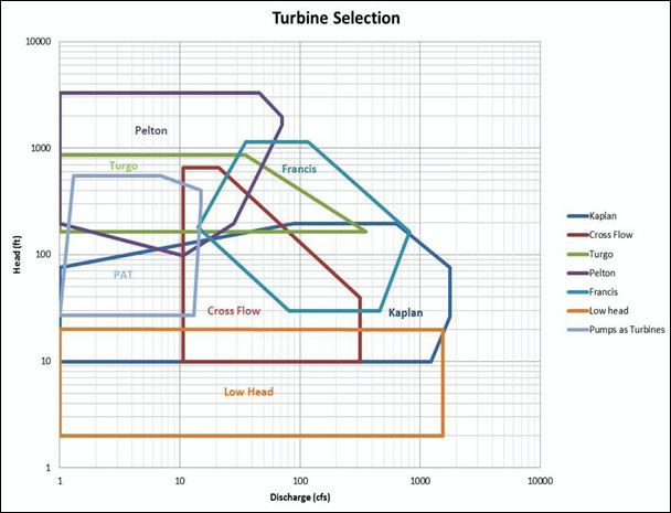
Source: The Colorado Energy Office “The Small Hydropower Handbook”
Both reaction and impulse turbines can operate over a wide range of flows as shown in Figure 33 and will generally have an operating range of 30 to 110 percent of the design flow. Generally, a flatter efficiency curve represents a turbine that can operate under broad ranges of head and flow. Curves that are steeper and narrower are indicative of a turbine designed for more focused ranges of operation. Efficiency curves specific to the type of turbine and design head and flow can be obtained from a manufacturer. These curves depict the relationship between the flow, head, and turbine efficiency under specific conditions. Use of these curves can be used to analyze how each turbine will perform under specific conditions. Turbine performance curves along with a flow duration curve can be used in the analysis of annual electric generation from the hydropower system.
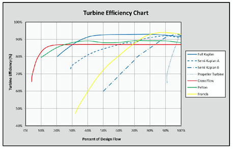
Source: The Colorado Energy Office “The Small Hydropower Handbook”