

A preliminary estimate of head and flow, as described in the previous section, is adequate for estimating the hydropower plant’s generating capacity in early stages of project development; however, as the project progresses, detailed and accurate measurements of head and flow are critical when determining the type of turbine and energy output of the generator.
Hydrology and Flow[i]
Flows available to a hydropower plant can either be estimated using the hydrologic conditions of the site or physically measured. The preferred method will depend on available data. Methods and resources are described below to estimate the flow conditions of a site. When using these methods, keep in mind available flows can change due to meteorological conditions. Forecasting future available flow requires careful consideration of past drought conditions and predicted climatic trends.
i) Historic Hydrology Data
Historic records of diversions may be available in instances where water is already diverted from a stream for agricultural, municipal or industrial uses under an existing water right. The Wyoming State Engineer’s Office maintains a public record of diversions by geographic area (see appendix for additional information). In cases when the hydropower facility will utilize a new diversion, water availability may be approximated by using flows from a nearby stream gauge. Real-time stream flow, through a GIS-based map and data portal, can also be accessed on the Wyoming State Engineer’s Office website (see appendix for additional information). Other stream gauges and data are kept by the United States Geologic Survey and can be downloaded from their website (see appendix). Average flows over multiple time periods can typically be accessed through the USGS database.
ii) Measurement of Flow
Measuring flow for a period during the planning stages of a hydropower plant may be necessary if historic records do not exist. There are structures to measure the flow rate in a channel. Reclamation provides guidance through its Water Measurement Manual.[ii] By using the structure’s dimensions, in conjunction with flow depths, a flow rate can be determined by referencing tabulate flow discharge values. The Reclamation manual has tabulated data in its appendices for three, commonly used flow measurement structures: the Parshall Flume, the weir, and the flow meter.
a) Parshall Flume
The Parshall Flume is one of the most common types of flumes in Wyoming, depicted in Figure 15. Canals are commonly measured using this type of flume. Use of a flume is likely the best alternative for flow measurement when water depth is low. For this particular type of measurement structure, a flume of known geometry is installed perpendicular to the flow in a channel. Using the measured water depth and throat width in the flume, an associated flow discharge can be calculated or obtained through reference to flow discharge tables (located in Appendix A8 of the Reclamation’s Water Measurement Manual).
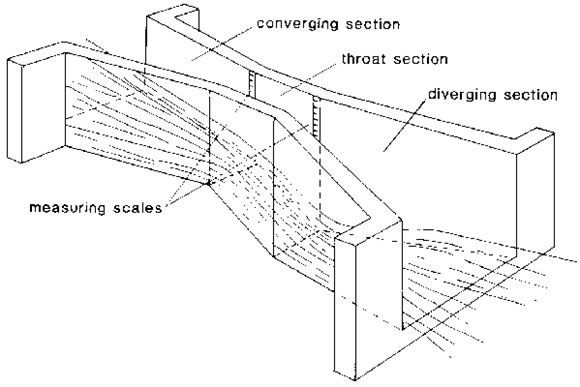
Source: Food and Agricultural Organization of the United States
b) Weir
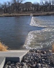
A weir is an overflow structure of known dimensions installed perpendicularly in the channel to measure the flow rate. Weirs are one of the most common measuring devices and are designed with various shapes and sizes, as shown in Figure 16, 17 and 18. Sharp-crested weirs have a center notch of varying shapes through which water is directed, while broad-crested weirs have a horizontal crest over which water flows. Using the upstream pool depth, weir dimensions, and depth of water flowing over the weir, the discharge flow rate can be calculated or obtained from a table. Guidance is provided in the aforementioned Reclamation manual.
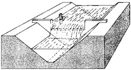
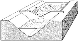
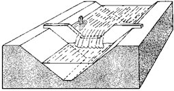
Source: Food and Agriculture Organization of the United Nations
c) Flow Meter
There are multiple types of flow meters. The most commonly used is the submerged orifice flow meter. This consists of a precisely designed, sharp-edged opening placed perpendicularly to the channel flow, through which all water passes. As small changes in the orifice’s construction can have a large impact on the accuracy of its associated flow values, the orifice must be well-machined and dimensioned as accurately as possible. By measuring the water depth immediately upstream and downstream of the orifice, flow rate can be obtained through the use of discharge tables. Guidance is provided in the aforementioned Reclamation manual.
d) Current Meter/Velocity Meter
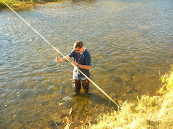
Flow measurement with a velocity meter measures the velocity of the channel flow. To measure flow, the current meter is placed at specific cross-section intervals along a reach of channel and records an average flow and water depth over those sections. The flow rate can then be calculated using the following equation:
Qi = Vi(Ai)
Where Qi = Flowrate in cubic feet per second at each cross-section interval
Vi = Velocity in feet per second at each cross-section interval
Ai = Cross-sectional area in square feet at each cross-section interval
The flow rate, Qi, at each interval is summed to obtain a total flow rate through the cross-section of the channel.
Optimally, current meters should be used in straight, uniform sections of the channel reach to minimize flow disturbances. Additionally, the flow velocity should be greater than 0.5 feet per second, and the meter should be kept as still as possible. This type of flow measurement is ideal for investigation of larger flows or for flows containing larger amounts of sediment. There are multiple types of current meters to measure the velocity of the channel flow:
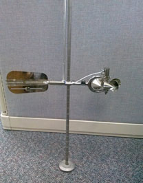
1) The Price Type AA meter is shown in Figure 19. This type of current meter is commonly used for irrigation and watershed applications. Velocity is measured by dragging anemometer cup wheels or propellers through calm waters.
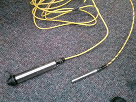
2) The electromagnetic velocity meter is shown in Figure 21. This type of current meter produces voltage proportionately to the stream velocity and has an easily read analog display. The measuring accounts for directional velocities and measure cross flows but is not as accurate as anemometer-propeller current meters.
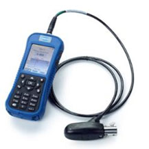
Source: Hach Company (www.hach.com)
3) The Acoustic Doppler Current Profiler is shown in Figure 22. These meters measure the change in source light or sound frequency to measure velocity. Doppler meters are versatile, providing measurement in a wide range of water body sizes and types. They are able to measure multiple directions of flow velocity simultaneously.
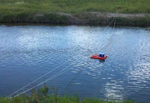
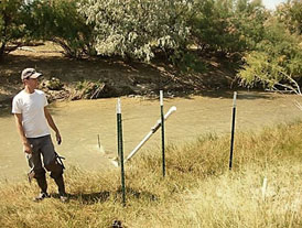
Multiple measurements throughout the planning period from the devices described above are needed to accurately determine the flow rate available for hydropower generation. Stream gauges that have continuous recording capabilities can be installed at weirs, flumes or channel reaches. The gauges generally consist of a water level sensor (pressure transducer), which logs the elevation of the water on a daily, hourly, or sub-hourly basis. The section of stream is then rated by measuring the flow from one of the methods described above to provide a relationship between the water surface elevation and the total flow. Stream gauges can be temporarily installed as shown in Figure 24 or permanent installations such as the USGS gauge shown in Figure 25.
[i] Source: The Colorado Energy Office. The Small Hydropower Handbook, August 2013 (www.colorado.gov/energy)
[ii] United States Department of the Interior, Bureau of Reclamation, Water Measurement Manual. 2001. (http://www.usbr.gov/pmts/hydraulics_lab/pubs/PAP/PAP-1058.pdf)