

Run-of-River Hydropower
Source: U.S. Department of Energy
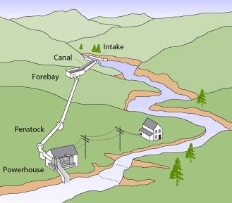
Run-of-river hydropower installations do not require large storage reservoirs and are commonly used for small hydropower systems. Run-of-river hydropower systems divert and convey a portion of a river’s water and convey the water through a channel or pressurized pipeline (penstock). The pressurized penstock then delivers the water to the hydropower turbine and is discharged back into the river. A schematic of a run-of-river hydropower installation is shown in Figure 6.
i) Strawberry Creek
The Strawberry Creek facility is a certified low-impact, run-of-river hydroelectric facility owned and operated by Lower Valley Energy on federal land in the Bridger-Teton National Forest near Bedford, Wyoming. The project consists of a concrete gravity dam 22 feet high and 110 feet long with a 40-foot long overflow spillway in the channel of Strawberry Creek. The dam diverts flows into a 2.3-mile long penstock and can supply up to 48 cfs for power generation. The powerhouse consists of three 500 kW Pelton turbines for a combined capacity of 1,500 kW. The turbines utilize 500 feet of head and 16 cfs each.
Conduit Hydropower
Conduit hydropower uses an already existing conduit (pipe or canal) that supplies water for purpose other than hydropower. Conduit hydropower systems are found in municipal water pipelines and irrigation distribution systems, where power can be generated from excess pressure that otherwise would have to be mechanically reduced by a pressure reducing valve. This type of hydropower plant is often very low impact and cost-effective, as they utilize existing infrastructure.
i) Garland Canal Power Plant
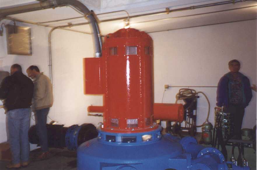
The Garland Canal Power Plant is owned and operated by the Shoshone Irrigation District near Ralston, Wyoming. The powerplant utilizes irrigation flows in the Garland Canal to generate power and consists of one semi-Kaplan turbine with a 2,900 kW generator. The powerplant was constructed in 1983 and utilizes 52 feet of head and 800 cfs.
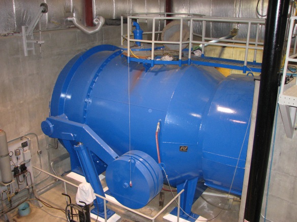
Photo courtesy of Shoshone Irrigation District
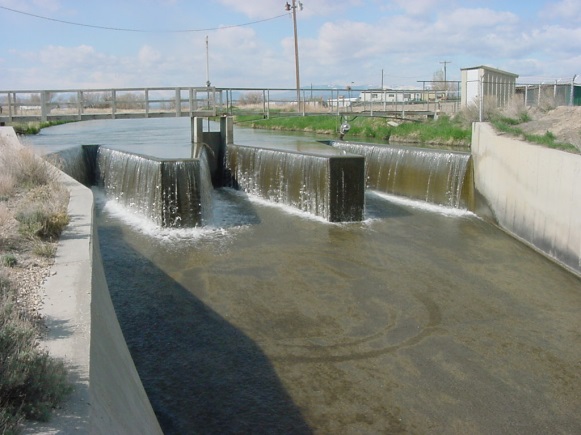
Photo courtesy of Shoshone Irrigation District
ii) Pilot Butte Powerplant
The Pilot Butte Powerplant is owned and operated by Reclamation and is part of the Riverton Unit. In 1951, Reclamation transferred the operation and maintenance of portions of the Riverton Unit to the Midvale Irrigation District but retained ownership and operation of the Pilot Butte Powerplant. The powerplant was constructed in 1925 at the drop from the Wyoming Canal to Pilot Butte Reservoir. The plant has two Francis turbines and generating units, which operate under a maximum head of 105 feet with a total capacity of 1,600 kW. The plant was shut down in 1973 because of high operation and maintenance costs and penstock problems. The penstock was replaced in 1990 and was placed back online until 2007 when shut down again due to high operation and maintenance costs. The high maintenance costs are a result of the age of the facility, as the powerplant and much of the other equipment is nearly 90 years old.
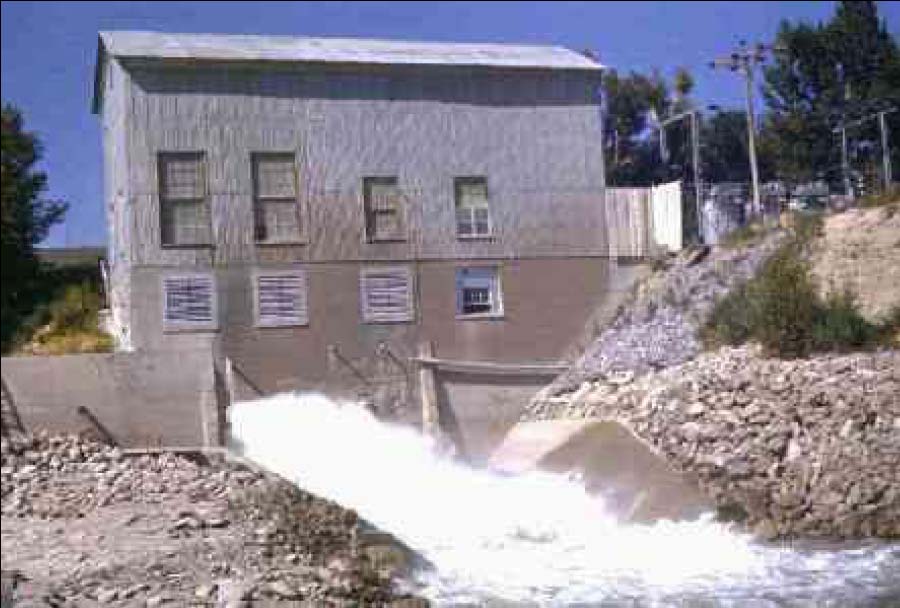
Source: U.S. Bureau of Reclamation
iii) Purvis Drop – Cody Canal Irrigation District
A study funded by the Wyoming Water Development Commission was recently completed assessing the feasibility of a hydropower facility at the Purvis Drop on the Cody Canal near Cody, Wyoming. The study concluded hydropower is potentially feasible. A new diversion structure in the canal at the top of the drop would divert water into the penstock. The penstock would run parallel to the existing canal drop and supply water to a Francis turbine at the bottom of the drop. The turbine would utilize 144 feet of head and up to 200 cfs to generate 1,660 kW. The turbine would then discharge water back into the canal at the bottom of the drop. The canal drop would handle overflows or flows when the turbine is offline.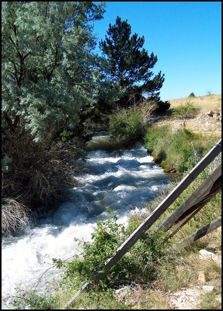
iv) Buffalo Hydropower Plant
The City of Buffalo owns and operates a 200 kW Pelton impulse type hydropower facility. The unit is inline with their existing 14-inch municipal raw water supply pipeline to the water treatment plant. The city diverts water from Clear Creek and pipes it 3.6 miles to the water treatment plant. In 1995, the diversion and pipeline were reconstructed in conjunction with the Tie Hack Reservoir. The hydropower facility was constructed in parallel with the existing pressure reducing station on the pipeline. This pipeline provides 6 cfs with 492 feet of net head to the hydro turbine. The hydropower facility is typically operated year-round. During snowmelt runoff and times when stream flows are adequate, the city uses its direct flow water rights to provide water to the turbine and water treatment plant. When stream flows are reduced and city direct flow water rights are out of priority, the City makes releases from storage in Tie Hack reservoir to provide water to the turbine and water treatment plant. During the non-irrigation season the municipal demand on the water treatment plant is reduced, and excess water from the hydro turbine is returned to Clear Creek.
v) Afton Culinary Water System Hydroelectric Facility
The Town of Afton and Lower Valley Energy co-own a 225 kW Pelton impulse type hydropower facility on Swift Creek in western Wyoming. The hydropower system was installed on their municipal water system, which is supplied by Periodic Spring. The pulsing flow from the spring can vary from no flow up to approximately 90 cfs during spring runoff. The existing municipal water supply system collects a portion of the flow and pipes it to a surge tank to help buffer the fluctuations. From the surge tank, flows enter an existing 3.2-mile long, 18-inch pipeline to the water treatment facility. The small hydro turbine was constructed in 2010 at the end of the pipeline and discharges to the water treatment facility storage tank. The hydro turbine makes use of 12 cfs and 310 feet of head to generate power.
vi) Sherard Hydroelectric Generation Project
The City of Cheyenne Board of Public Utilities is evaluating adding a hydropower unit in parallel with its existing pressure reducing station at the head of the water treatment plant. The water treatment plant is supplied from Crystal Lake Reservoir via a 15 mile long pipeline. Head and flow conditions vary based on the demand of the water treatment plant. Flows can range as high as 35 cfs during peak demand and averages 10 cfs during the non-irrigation months. Available head varies due to head loss in the existing pipeline and ranges from 440 feet at 35 cfs to 500 feet at 10 cfs. At 20 cfs there is 490 feet of net head available. Preliminary turbine selection indicates either a single impulse type turbine or single Francis type turbine would be appropriate. Rated capacity would likely be approximately 700 kW at 20 cfs.